
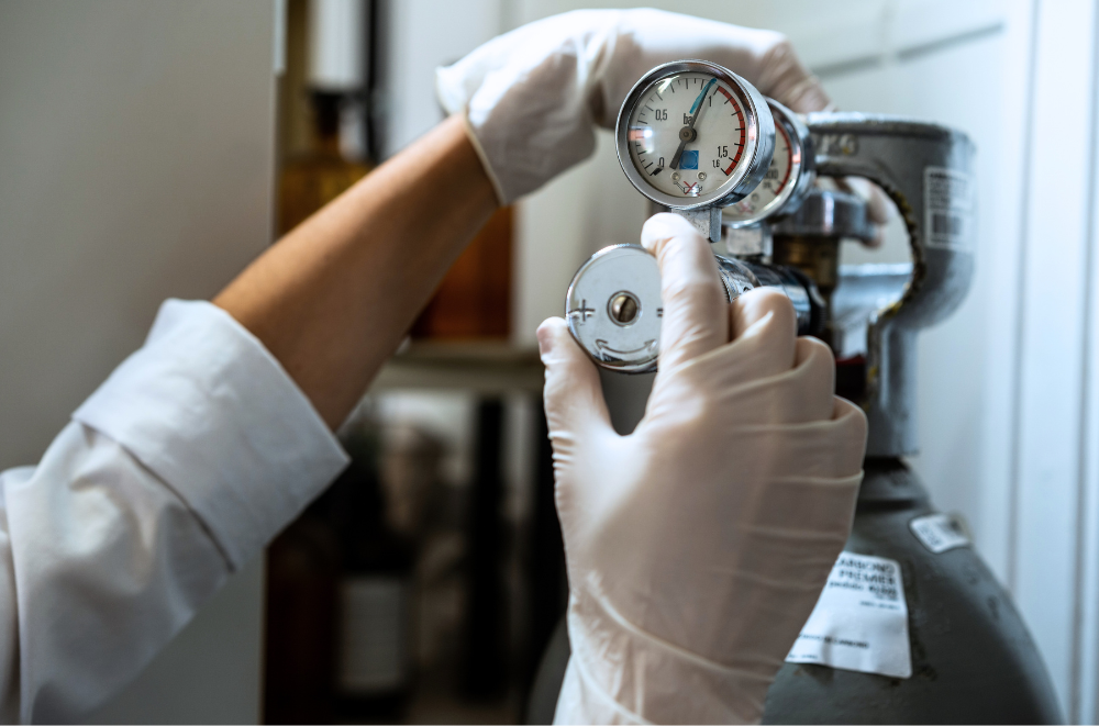
When a flame ionization detector will not ignite, repeatedly goes out, or produces a noisy or elevated baseline, check the actual hydrogen and air flows, supply pressures, gas purity, leaks, and gas-line condition. However, do not assume that every FID problem comes from the gas source. A dirty or incorrectly installed jet, failed ignitor, detector contamination, column bleed, inlet contamination, poor electrical connections, and incorrect temperature can produce similar symptoms.
The fastest troubleshooting approach is to separate the problem into three questions:
-
Can the FID ignite and remain lit? Check temperature, ignition, actual hydrogen and air flow, pressure, gas ratio, leaks, and the jet.
-
Is the lit detector background unusually high or noisy? Check gas purity and traps, then isolate the column, makeup gas, detector contamination, and electrometer.
-
Did the problem begin after a gas-cylinder change, generator installation, maintenance, or plumbing work? Investigate the most recent change first.
The exact procedures and acceptable limits vary by GC model. Always follow the current instrument manual and laboratory safety procedures before adjusting flows, disconnecting a column, measuring gas flow, or servicing the detector.
What Does Hydrogen Do in an FID?
A flame ionization detector burns hydrogen in air at the detector jet. Organic compounds exiting the GC column enter the flame and form ions; the collector measures the resulting current. Because the FID responds to ions formed from carbon-containing compounds, hydrocarbons introduced through the hydrogen, combustion air, makeup gas, carrier gas, dirty tubing, or leaks can raise background and interfere with low-level measurements.
Hydrogen and air perform different roles:
|
Gas |
FID function |
Problems associated with supply or quality |
|
Hydrogen |
Fuel for the flame |
Failure to ignite, unstable flame, inadequate flow, high background if hydrocarbon-contaminated |
|
Air or zero air |
Oxidizer for the flame |
Failure to ignite, flame instability, high background if hydrocarbons are present |
|
Makeup gas |
Optimizes detector flow and response |
Incorrect response, ignition difficulty in some configurations, noise or background if contaminated |
|
Carrier gas |
Brings analytes from the column into the detector |
Retention and separation problems; background from contaminated gas or column bleed |
The Agilent GC site-preparation guide recommends detector gases with minimum purity of 99.9995%, zero-grade air or better for the FID, and high-quality traps to remove hydrocarbons, moisture, and oxygen. These are manufacturer recommendations for the cited Agilent systems, not universal specifications for every GC. Use the requirements published for the exact instrument and application.
Quick Diagnostic Table
|
Symptom |
Possible gas-related causes |
Other common causes |
First checks |
|
FID will not ignite |
No hydrogen or air; inadequate pressure; incorrect flow ratio; leak; wet or contaminated gas |
Failed ignitor; low detector temperature; blocked or incorrect jet |
Confirm supplies, pressure, temperature, ignitor operation, and actual flows |
|
Flame ignites but goes out |
Unstable supply; pressure drop; incorrect hydrogen-to-air balance; leak |
Partially blocked jet; excessive column or makeup flow; detector fault |
Measure flows during ignition and normal operation; leak-check; inspect jet |
|
High baseline |
Hydrocarbons in H2, air, makeup gas, tubing, or traps |
Column bleed; dirty inlet or detector; high detector output/leakage current |
Review recent gas changes; isolate column and makeup gas; inspect detector |
|
Noisy baseline |
Supply-pressure fluctuations; contaminated gas; exhausted traps; leaks |
Electrical leakage; dirty collector or insulators; column or inlet contamination |
Run the manufacturer’s noise test; inspect gas system; isolate components |
|
Baseline drifts upward |
Changing gas contamination or trap performance |
Column bleed during temperature programming; detector contamination; incomplete conditioning |
Compare blank and temperature-program behavior; inspect traps and column |
|
Frequent problems after cylinder changes |
Regulator contamination; air entering lines; wrong grade gas; poor purging |
Coincidental instrument or column issue |
Verify cylinder grade, regulator, connections, purge, and leak integrity |
Why Won’t the FID Ignite?
An FID needs the correct detector temperature, a functioning ignitor, an open gas path, adequate supply pressure, and an ignitable hydrogen-to-air mixture. If any of these conditions is missing, the flame may fail to light.
The Agilent Intuvo 9000 troubleshooting manual instructs users to check detector temperature, hydrogen and air pressure, actual detector flows, the hydrogen-to-air ratio, the jet, and column connections. It notes that nonoptimal flows can prevent ignition and that measured flows for the cited system should be within ±10% of their setpoints.
Thermo Fisher’s FID flame-ignition troubleshooting guidance similarly recommends checking the ignitor, gas purity and flow, leaks, line purging, detector maintenance, and the FID jet. Agreement across instrument manufacturers reinforces the value of checking the complete gas path rather than immediately replacing one component.
Check detector temperature
Many GCs inhibit or complicate FID ignition when the detector is too cool. Confirm that the detector has reached the manufacturer’s minimum ignition temperature and that its temperature reading is credible. Do not apply a temperature threshold from another GC model without checking the applicable manual.
Confirm hydrogen and air supplies
Verify that:
- The hydrogen source is on and not in an alarm or shutdown condition.
- The air source or compressor is operating.
- Regulators and shutoff valves are open and correctly set.
- The generator has adequate capacity for every detector operating simultaneously.
- Supply pressure remains adequate while gas is flowing.
- No maintenance valve, manifold branch, or instrument channel is unintentionally closed.
A static regulator reading does not prove that adequate pressure reaches the detector under flow. Pressure can fall because of an undersized source, a restrictive filter, long or narrow tubing, a failing regulator, multiple instruments drawing simultaneously, or a partially closed valve.
Measure actual flows
Displayed setpoints are not a substitute for measuring detector flow when ignition problems persist. Agilent’s troubleshooting guidance directs users to measure hydrogen, air, and makeup flows separately and compare actual flow with the programmed value.
Use only the GC manufacturer’s approved procedure and a flowmeter suitable for the gas and range. Never combine hydrogen and air in a flowmeter. Agilent explicitly warns that hydrogen and air should be measured individually because the mixture can be explosive.
Check the hydrogen-to-air balance
An FID may have hydrogen and air present but still fail to ignite if their ratio is unsuitable. Do not permanently change a validated method simply to force ignition. Follow the manufacturer’s approved ignition procedure, then return flows to established operating settings and confirm system performance.
Inspect the jet and ignitor
A partially plugged jet changes actual gas flow and flame geometry. An incorrectly installed jet or one intended for a different column configuration can also create problems. Confirm that the correct jet is installed, inspect it using the manufacturer’s procedure, and clean or replace it as directed.
Observe the ignitor only as described in the instrument manual. If it does not glow or otherwise operate during the ignition sequence, check its cable and replace it according to the manufacturer’s service instructions.
Leak-check the gas path
Leaks can reduce delivered flow, admit contaminants, and create a flammable-hydrogen hazard. Leak-check the approved connection points with the specified method, paying particular attention to recent work, regulators, traps, manifolds, and the column connection at the detector.
Shimadzu’s hydrogen precautions for FID, FPD, and FTD detectors state that users should stop hydrogen flow and inspect the detector if ignition fails, rather than allowing hydrogen to continue flowing while repeatedly attempting ignition. Follow the shutdown sequence for the specific GC.
Why Does the Flame Keep Going Out?
A flame that lights but will not remain stable often points to marginal flow, pressure, or gas balance. It can also indicate a restricted jet, excessive column or makeup flow, a leak, contamination, or an instrument fault.
Check whether the flame loss correlates with:
- Another GC beginning a run.
- Simultaneous detector ignition.
- Generator alarms or water-level warnings.
- Compressor cycling.
- A cylinder approaching depletion.
- Oven-temperature changes.
- High split or carrier-gas demand.
- Changes to detector or makeup flow.
- Recent trap or regulator replacement.
A shared gas source can appear satisfactory during idle conditions yet lose pressure when several instruments draw simultaneously. If the problem appears only at peak use, compare aggregate demand with generator capacity and measure delivered pressure at the most distant or most demanding GC.
Organomation’s GC-FID hydrogen-generator sizing guide explains how to total simultaneous detector demand and verify pressure. Capacity should be based on peak credible usage—not average consumption or GC count alone.
How Gas Quality Affects Baseline
The FID responds to organic material regardless of whether it arrives from the sample or the gas supply. Hydrocarbons in hydrogen, air, carrier gas, or makeup gas therefore contribute to background signal. Contaminated tubing, regulators, and exhausted traps can also introduce organic compounds downstream from an otherwise clean source.
Agilent’s FID noise and high-background troubleshooting guide identifies organic material in carrier gas, makeup gas, FID air, hydrogen, and column stationary-phase bleed as contributors to FID background. Its recommended workflow begins by confirming gas purity and checking the delivery system for leaks before isolating the column, makeup gas, and detector components.
Thermo Fisher likewise notes in its FID analyzer guidance that hydrocarbon-contaminated fuel or air can increase FID background and interfere with low-level hydrocarbon measurement. Although that document addresses an analyzer rather than a conventional GC detector, the underlying issue is the same: background hydrocarbons entering the flame produce signal.
Hydrogen contamination
Hydrogen may meet a broad purity grade yet still be unsuitable if its hydrocarbon, moisture, or oxygen content exceeds the instrument or method requirement. Evaluate the full contaminant specification—not only total purity.
The Claind H Series hydrogen generator publishes 99.9999% hydrogen purity, oxygen below 1 ppm, and a dew point better than -70°C under the stated conditions. It is available in nominal 200, 400, and 600 mL/min models. Laboratories should verify that purity, pressure, and capacity meet the requirements of the connected GCs.
Zero-air contamination
Zero air is combustion air from which hydrocarbons have been reduced to a level suitable for the detector. It is not interchangeable with ordinary plant compressed air unless the air has been properly treated and validated for the application.
Agilent specifies zero-grade air or better for the FID in its current site-preparation documentation. Shared plant air can contain compressor oil, water, particles, and ambient hydrocarbons unless suitable drying, filtration, and catalytic treatment are installed.
The Claind AirGen GC zero-air generator is rated at 3,000 mL/min ±10% and publishes residual total hydrocarbons below 0.1 ppm using a PSA dryer and platinum-palladium catalytic reactor. Organomation positions it for as many as eight FIDs, but the number supported must be verified against the actual air settings and simultaneous operation of the laboratory’s instruments.
Tubing and traps
Clean source gas can become contaminated before reaching the detector. Potential causes include:
- Old or contaminated tubing.
- Hydrocarbon-containing thread compounds or sealants.
- Dirty regulators and manifolds.
- Saturated hydrocarbon, oxygen, or moisture traps.
- Back-diffusion of laboratory air during cylinder changes.
- Inadequate purging after maintenance.
- Leaking fittings.
The Agilent 8850 site-preparation guide warns that hydrogen can remove contaminants left in previously used tubing, potentially causing high background or hydrocarbon contamination for an extended period. Use new chromatographic-quality tubing and fittings where the instrument manufacturer requires them, especially during a change to hydrogen service.
Noise vs. High Background
“Noise” and “high background” are related but not identical.
- High background is an elevated average detector signal, often associated with organic contamination, column bleed, or a dirty detector.
- Noise is short-term signal variation around the baseline and can come from unstable gas delivery, contamination, electrical leakage, or detector problems.
- Drift is a gradual directional change and often correlates with temperature, conditioning, column bleed, contamination, or changing gas quality.
The visual appearance of the chromatogram alone rarely identifies the source. Use the instrument’s formal noise test where available, record the background with the flame lit and extinguished as directed, and isolate system components methodically.
A Step-by-Step Workflow
Step 1: Review recent changes
Ask what changed immediately before the problem began:
- New hydrogen or air cylinder.
- New generator or compressor.
- Trap replacement.
- Regulator adjustment.
- Tubing installation.
- Column replacement.
- Detector cleaning.
- New method or flow settings.
- Maintenance or power interruption.
A sudden problem usually deserves a change-focused investigation before broad component replacement.
Step 2: Read alarms and status data
Check the GC, hydrogen generator, zero-air generator, and compressor for alarms, low water, maintenance warnings, pressure faults, or unusual cycling. Record conditions before resetting alarms so the evidence is not lost.
Step 3: Verify pressure under load
Check pressure while all instruments expected to operate simultaneously are drawing gas. If pressure is adequate at the source but low at the GC, inspect the distribution system for restrictions, an undersized regulator, exhausted traps, long tubing, or excessive shared demand.
Step 4: Measure detector flows
Measure hydrogen, air, and makeup flows independently using the manufacturer-approved procedure. Compare the results with the GC setpoints and manual tolerances. A discrepancy can indicate low supply pressure, a leak, restriction, failed flow-control component, or blocked jet.
Step 5: Leak-check recent and critical connections
Prioritize the detector column connection, regulator, traps, manifolds, generator outlet, and fittings disturbed during recent work. Stop and correct any hydrogen leak before continuing.
Step 6: Check gas grades and traps
Confirm cylinder certificates or generator specifications, trap types, installation direction, service dates, and indicator status. If a problem began immediately after changing a cylinder, regulator, or trap, reconsider that change.
Step 7: Isolate the column and makeup gas
Follow the GC manufacturer’s exact procedure. Agilent’s troubleshooting sequence removes or isolates the column first; if the detector then passes its noise test, suspect the column or carrier-gas path. If noise remains, turning off makeup gas can help identify contaminated makeup gas. These tests should only be performed according to the manual for the specific instrument.
Step 8: Evaluate detector contamination and electronics
If gas-path checks and isolation tests do not resolve the problem, inspect the jet, collector, insulators, interconnects, and electrometer as instructed by the manufacturer. Leakage current or contamination can produce noise even when gas supplies are clean.
Step 9: Requalify performance
After correcting the problem, document:
- Successful ignition and flame stability.
- Actual hydrogen, air, and makeup flows.
- Delivered pressure under peak demand.
- Blank background, noise, and drift.
- Retention-time and response repeatability.
- System suitability and applicable QC samples.
- Work performed and parts or traps replaced.
When a Generator Can Help
An on-site hydrogen or zero-air generator can address several supply-related problems:
- Cylinder depletion during unattended sequences.
- Pressure disturbances during cylinder changeover.
- Inconsistent cylinder inventory and delivery.
- Contamination introduced during repeated regulator changes.
- Excessive stored-cylinder handling.
- Inadequate treatment of ordinary compressed air for FID use.
A generator will not correct:
- A failed ignitor.
- A plugged or incorrect jet.
- A dirty collector or insulator.
- Column bleed.
- Inlet contamination.
- Incorrect detector temperature.
- A leaking column connection.
- Electrometer or flow-control failure.
- Incorrect method settings.
Balanced troubleshooting is important. Recommending a gas generator before confirming that the problem lies in gas delivery can waste time and reduce confidence. The stronger approach is to verify the failure mode, then specify a generator that meets the laboratory’s peak flow, pressure, purity, and continuity requirements.
Hydrogen and Zero-Air Pairing
A complete generated-gas system can supply both sides of the FID flame:
|
Requirement |
Claind option |
Published specification |
|
Hydrogen detector fuel |
200, 400, or 600 mL/min; purity up to 99.9999%; oxygen below 1 ppm |
|
|
Zero air for smaller multi-FID installations |
3,000 mL/min; residual total hydrocarbons below 0.1 ppm |
|
|
Zero air for larger installations |
5 or 20 L/min; residual total hydrocarbons below 0.1 ppm |
These products should be sized independently. FID air demand is typically much greater than hydrogen demand, and exact settings vary by GC and method. Include all detectors that can operate simultaneously and verify pressure at the instruments under full load.
Frequently Asked Questions
Why will my FID not ignite?
Common causes include no hydrogen or air, inadequate supply pressure, an unsuitable hydrogen-to-air balance, leaks, low detector temperature, a blocked or incorrect jet, and a failed ignitor. Confirm actual flows rather than relying only on setpoints.
Why does my FID flame keep going out?
The flame may be operating near the edge of a stable flow or pressure range. Check for pressure drops during peak demand, incorrect flows, leaks, a partially blocked jet, excessive column or makeup flow, gas-source alarms, and flow-control faults.
Can poor hydrogen quality cause a noisy FID baseline?
Yes. Hydrocarbon contamination in hydrogen can raise FID background, while moisture, contamination, pressure instability, or delivery-system problems may contribute to unstable performance. However, column bleed, dirty detector parts, inlet contamination, and electrical leakage are also common causes.
Can ordinary compressed air be used for an FID?
Only if it is treated and verified to meet the GC manufacturer’s requirements. Agilent specifies zero-grade air or better for its cited FID systems. Untreated plant air may contain oil, moisture, particles, and hydrocarbons that can contaminate the detector and elevate background.
What is zero air?
Zero air is purified air with hydrocarbons reduced to a low specified level for analytical use. The exact allowable total-hydrocarbon content depends on the instrument and application. A zero-air generator typically uses drying, filtration, and catalytic oxidation to remove contaminants.
Does zero air eliminate all baseline noise?
No. Clean combustion air removes one potential source of FID background and instability. Baseline performance also depends on hydrogen, makeup and carrier gases, column bleed, inlet cleanliness, detector condition, electronics, method conditions, and the gas-delivery system.
How can contaminated makeup gas be identified?
Use the instrument manufacturer’s isolation procedure. Agilent recommends repeating the noise test with makeup gas turned off after the column has been isolated; improvement can indicate contaminated makeup gas. Do not improvise this test on a different GC platform.
Should hydrogen, air, and makeup flow be measured together?
No. Measure each gas separately using the manufacturer’s approved method. Mixing hydrogen and air in a flowmeter can create a hazardous combustible mixture.
Will replacing cylinders with generators improve baseline stability?
It may improve consistency if cylinder changes, regulator problems, gas contamination, or inadequate air treatment are causing the instability. A generator is not a universal baseline repair; the full system should be diagnosed first.
What should be checked after installing a gas generator?
Verify gas purity and specifications, delivered pressure under maximum demand, actual detector flows, leak integrity, blanks, baseline noise and drift, detector response, system suitability, alarms, shutdown functions, and required change-control documentation.
Diagnose Before Replacing
Hydrogen and zero-air quality directly affect FID ignition and background, but they are only part of the detector system. Begin with actual flow, pressure, purity, and leak checks; then isolate the column, makeup gas, detector contamination, and electronics according to the GC manufacturer’s procedure.
If gas delivery is the confirmed weakness, an appropriately sized hydrogen generator and zero-air generator can remove cylinder changeovers, provide an on-demand supply, and reduce exposure to inconsistent gas handling. The generator must still be matched to the laboratory’s peak simultaneous demand, instrument pressure, purity requirements, and uptime needs.
Organomation can review GC models, detector count, hydrogen and air settings, simultaneous operation, existing gas plumbing, and baseline symptoms to identify whether generated gas is an appropriate part of the solution.