
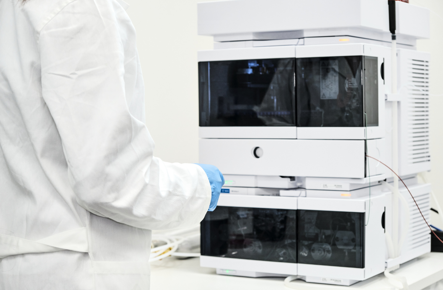
The correct hydrogen generator for a GC-FID laboratory is determined by maximum simultaneous hydrogen flow, required delivery pressure, gas purity, other hydrogen-consuming equipment, and expansion plans. Do not select a generator from the number of GCs alone: two laboratories with four instruments can have very different demand if one operates all four FIDs continuously while the other rarely runs more than two.
For detector-fuel-only installations, start with this calculation:
Required detector flow = hydrogen flow per FID × maximum number of FIDs operating simultaneously
Then add any other hydrogen demand and enough unused capacity for startup behavior, flow variation, distribution losses, and reasonable expansion. The final selection must also satisfy the GC manufacturer’s pressure and purity requirements at the instrument—not merely the generator’s rated outlet.
Quick Sizing Answer
Many conventional FID methods operate near 30–40 mL/min of hydrogen per detector, but published ranges vary by GC model and configuration. The Agilent 8890/8850 operation manual recommends 40 mL/min as a starting condition for its FID, while a Shimadzu GC-2030 FID application uses 32 mL/min. Agilent’s 7890B documentation lists 30 mL/min as a suggested setting for several standard configurations and an operating range of 24–60 mL/min.
The practical implication is simple: use the actual hydrogen setting and supply requirement for each GC, not a generic industry average.
As a preliminary guide, a laboratory operating FIDs near 40 mL/min might consider the following—not as guaranteed model assignments, but as starting points for technical review:
|
Simultaneous FIDs |
Nominal detector demand at 40 mL/min each |
Preliminary capacity discussion |
|
1 |
40 mL/min |
H 200 provides substantial unused nominal capacity |
|
2 |
80 mL/min |
H 200 may be suitable after pressure and reserve review |
|
3 |
120 mL/min |
H 200 may fit, but future expansion and operating margin become more important |
|
4 |
160 mL/min |
H 200 approaches its nominal capacity; H 400 is generally the more flexible starting point |
|
5–8 |
200–320 mL/min |
H 400 or H 600 should be evaluated based on actual simultaneous demand and expansion |
|
More than 8 |
More than 320 mL/min |
H 600 or a validated parallel configuration may be appropriate |
This table assumes detector fuel only. It does not include hydrogen carrier gas, FPD or NPD demand, another analyzer, line losses, method-specific higher flows, or a redundancy requirement. Claind rates the H Series at 200, 400, or 600 Nml/min with a stated ±10% tolerance, so nominal capacity should not be treated as a target for continuous laboratory demand.
What Determines Generator Size?
Five factors control generator selection:
-
Hydrogen flow per detector. Use the value in the active GC method or the instrument manufacturer’s starting conditions.
-
Maximum simultaneous operation. Size for the busiest realistic operating condition, not average usage.
-
Other hydrogen demand. Include carrier gas, other detectors, analyzers, or instruments connected to the same source.
-
Pressure at peak flow. Confirm that adequate pressure reaches the most demanding and most distant GC while all connected instruments are operating.
-
Operating reserve and expansion. Leave capacity for normal variation, ignition behavior, future instruments, and changes in laboratory scheduling.
Purity, utilities, installation environment, and continuity strategy can disqualify an otherwise adequate flow rating. Generator sizing is therefore a system-design task, not simply a multiplication exercise.
How Much Hydrogen Does an FID Use?
FID hydrogen flow depends on the instrument and configuration. Manufacturer-published examples demonstrate why a universal value should not be used:
|
Manufacturer source |
Published FID hydrogen information |
How to use it |
|
40 mL/min suggested starting flow; hydrogen-to-air ratio of 8–12% identified for maintaining the flame |
Starting point for the cited system, not a universal specification |
|
|
30 mL/min suggested for several standard configurations; 24–60 mL/min operating range for the cited FID |
Shows potential variation within one instrument family |
|
|
32 mL/min H2, 200 mL/min air, and 24 mL/min nitrogen makeup gas |
Method-specific example, not a sizing rule |
|
|
Electronic hydrogen-flow range of 0–100 mL/min for the FID |
Demonstrates the wider control envelope available on some instruments |
The best sizing input is the laboratory’s actual method setting, confirmed against the current instrument manual. If methods use different FID flows, calculate the highest credible simultaneous combination rather than multiplying every detector by a single assumed value.
How Do You Calculate Total Demand?
For a detector-fuel-only system:

If the generator also supplies hydrogen carrier gas or another application:

The selected generator must provide more usable capacity than the calculated base demand under the actual installation conditions. Claind publishes a ±10% flow tolerance for the H Series, which means selection should not assume that every unit will always deliver exactly the nominal nameplate flow.
Example: Two GC-FIDs
A laboratory operates two FIDs at 35 mL/min each, and both can run simultaneously:
- FID 1: 35 mL/min
- FID 2: 35 mL/min
- Base demand: 70 mL/min
An H 200 has ample nominal flow above this base demand, assuming its pressure, purity, utilities, and installation requirements are also satisfied.
Example: Four GC-FIDs
A laboratory operates four FIDs at 40 mL/min:
- Four detectors × 40 mL/min
- Base demand: 160 mL/min
Although 160 mL/min is below the H 200’s 200 Nml/min nominal rating, the remaining nameplate capacity is only 40 mL/min before considering the published flow tolerance, other demand, expansion, or the laboratory’s desired reserve. An H 400 would normally provide a more flexible design starting point, but the final recommendation should follow a complete demand and pressure review.
Example: Eight GC-FIDs
A laboratory operates eight FIDs at 35 mL/min:
- Eight detectors × 35 mL/min
- Base demand: 280 mL/min
An H 400 is nominally above the calculated detector demand, but an H 600 may be preferable if all detectors are critical, higher-flow methods are possible, new instruments are planned, or the laboratory wants more operating headroom. Redundancy is a separate question: a larger single generator provides more capacity but does not eliminate a single point of failure.
How Much Reserve Capacity Is Needed?
There is no defensible universal reserve percentage for every GC-FID installation. The appropriate margin depends on:
- Manufacturer-stated generator tolerance.
- Normal versus maximum FID settings.
- Ignition and startup behavior.
- Number of detectors starting simultaneously.
- Pressure drop across the distribution system.
- Elevation and environmental limits in the generator specification.
- Future GC purchases.
- Whether the same generator supplies carrier gas.
- Operational consequences of low pressure or generator shutdown.
Avoid sizing a generator to run continuously at or near its nominal limit. Claind identifies its H Series flow as 200, 400, or 600 Nml/min ±10%, which alone argues against treating the nameplate value as guaranteed spare-free capacity. Organomation should establish the final configuration from an application questionnaire and, for larger installations, a written gas-demand schedule.
Why Pressure Matters as Much as Flow
A generator can have enough total flow and still be unsuitable if it cannot maintain the required pressure at the GC. The Agilent GC site-preparation guide specifies a detector hydrogen delivery range of 35–100 psig for its cited systems and requires sufficient differential pressure for flow- and pressure-control devices to operate correctly. It also explains that supply pressure should be measured at the instrument because line losses can make source pressure misleading.
The Claind H Series publishes an adjustable outlet range of 2–8 bar, or 30–116 psi. That range overlaps common GC requirements, but compatibility must be checked for each instrument. A generator set to an appropriate source pressure must still overcome:
- Tubing length and internal diameter.
- Filters and traps.
- Valves, manifolds, and fittings.
- Elevation changes.
- Peak simultaneous flow.
- Pressure requirements of the most demanding GC.
The most distant instrument is often the best place to verify delivered pressure under full-load conditions. For multi-GC installations, locating an auxiliary pressure gauge or regulator close to the instruments may improve commissioning and troubleshooting.
H 200 vs. H 400 vs. H 600
Organomation’s Claind H Series hydrogen generators share the same published purity and outlet-pressure range but differ in maximum nominal flow and power consumption.
|
Model |
Nominal flow |
Outlet pressure |
Published purity |
Electrical power |
|
H 200 |
200 Nml/min ±10% |
2–8 bar / 30–116 psi |
99.9999%; O2 below 1 ppm |
110 W |
|
H 400 |
400 Nml/min ±10% |
2–8 bar / 30–116 psi |
99.9999%; O2 below 1 ppm |
180 W |
|
H 600 |
600 Nml/min ±10% |
2–8 bar / 30–116 psi |
99.9999%; O2 below 1 ppm |
250 W |
The manufacturer’s H Series specifications also permit parallel connection of as many as four stackable modules. Parallel capacity can support larger demand or phased expansion, but Organomation and Claind should confirm how the proposed configuration handles load sharing, controls, maintenance isolation, and fault response.
When the H 200 fits best
The H 200 is the logical starting point for smaller detector-fuel installations where calculated demand remains comfortably below 200 Nml/min. Typical candidates may include one to three standard-flow FIDs, although actual method flows and future plans determine the final fit.
When the H 400 fits best
The H 400 is better suited to laboratories with several simultaneously operating FIDs, limited near-term expansion, or a demand profile that leaves too little unused capacity on the H 200. It may also suit mixed use when the generator supports detector fuel plus a modest, fully calculated additional hydrogen load.
When the H 600 fits best
The H 600 is the strongest single-module option for larger multi-GC laboratories, higher combined demand, or organizations expecting expansion. It may also provide more flexibility where instrument scheduling varies substantially, although higher capacity should not be confused with redundancy.
Detector Fuel vs. Carrier Gas
Sizing changes substantially if hydrogen serves as both FID fuel and GC carrier gas.
For detector fuel only, the calculation includes the hydrogen flowing to each detector flame. If hydrogen is also the carrier, include column flow plus inlet split and purge behavior as applicable to the GC architecture. High split ratios can create gas demand that is not apparent from column flow alone unless the instrument uses gas-saving technology.
The laboratory should therefore answer one question before requesting a quote:
Is the generator supplying detector fuel only, or detector fuel plus carrier gas?
Organomation’s article on replacing GC-FID hydrogen cylinders without changing the GC method addresses the simpler detector-fuel-only use case. Laboratories evaluating carrier-gas conversion should use a separate demand calculation and method-compatibility review.
Can One Generator Supply Multiple GCs?
Yes—provided it can maintain the required purity, pressure, and maximum simultaneous flow at every connected instrument. Centralizing hydrogen supply can simplify cylinder replacement and gas management, but it introduces design questions that do not arise with one generator per GC.
Evaluate:
- Total peak demand, not average use.
- Pressure at the furthest GC.
- Isolation valves for each instrument branch.
- Clean, hydrogen-compatible tubing and fittings.
- Ability to service one GC without depressurizing the entire network.
- Generator maintenance downtime.
- Consequences of one generator fault affecting all GCs.
- Future instruments and unused branch capacity.
The Agilent site-preparation guide accepts gas from cylinders, internal distribution systems, or gas generators, but emphasizes correct supply pressure, clean plumbing, and sufficient pressure differential at the instrument.
Do Startup and Ignition Affect Sizing?
They can. The FID must receive an appropriate hydrogen-to-air balance to ignite and remain lit. Agilent’s troubleshooting documentation notes that insufficient supply pressure can make ignition more difficult and recommends measuring actual detector flow when diagnosing flame problems. It also states that measured flows should remain within ±10% of their setpoints for the cited system.
This does not establish a universal startup multiplier. Instead, it reinforces three practical requirements:
- Do not size at the exact nominal steady-state total.
- Avoid starting every detector simultaneously until the installation has been qualified.
- Verify actual flow and pressure during the laboratory’s most demanding operating condition.
If an existing installation has recurring ignition failures, do not assume a larger generator is automatically the solution. Incorrect gas ratios, a blocked jet, leaks, detector temperature, ignitor failure, and plumbing problems can produce similar symptoms.
What Purity Should the Generator Provide?
The generator must meet the most stringent requirement among the connected instruments and methods. Agilent’s site-preparation materials recommend chromatographic-quality carrier and detector gases and zero-grade air for flame detectors. The Claind H Series publishes 99.9999% hydrogen purity, oxygen below 1 ppm, and dew point better than -70°C under stated conditions.
Purity at the generator outlet is only part of the system. Delivered gas quality also depends on:
- New, clean tubing.
- Hydrogen-compatible valves and fittings.
- Installation practices.
- Appropriate traps where specified.
- Leak integrity.
- Avoidance of hydrocarbon contamination.
- Preventive maintenance.
Agilent recommends new chromatographic-quality copper or stainless-steel tubing for hydrogen installations and advises against reusing old tubing. Follow the requirements of the exact GC model and facility safety program.
What About Zero Air?
FID hydrogen capacity and zero-air capacity must be sized separately. The detector generally consumes much more air than hydrogen: the cited Agilent starting condition is 40 mL/min hydrogen, with the hydrogen-to-air relationship controlled to maintain a stable flame. Some methods and instruments use different air settings, as shown by Shimadzu’s 32 mL/min hydrogen and 200 mL/min air application example.
If the laboratory also wants to eliminate air cylinders, review Organomation’s zero-air generators for analytical chemistry. Do not assume that a zero-air generator supporting a stated number of detectors will necessarily match every laboratory; calculate maximum simultaneous air demand using the actual GC settings.
Redundancy vs. Extra Capacity
Extra flow capacity and redundancy solve different problems:
|
Design choice |
What it provides |
What it does not provide |
|
Larger single generator |
More unused flow and room for expansion |
Continued supply during generator shutdown |
|
Two separate generators serving different GCs |
Segmentation of instrument risk |
Automatic backup for either group unless specially engineered |
|
Parallel generator configuration |
Scalable combined capacity |
Guaranteed redundancy unless controls and isolation support it |
|
Standby generator |
Potential backup supply |
Immediate failover unless validated switching is provided |
Laboratories running compliance samples, unattended sequences, or high-value production work should include the cost of interrupted detector operation in the sizing decision. A larger model may reduce capacity risk, but continuity planning requires maintenance procedures, alarm response, spare consumables, and—where justified—an engineered backup strategy.
GC-FID Sizing Worksheet
Before requesting a recommendation, collect the following information:
|
Input |
Laboratory value |
|
GC manufacturer and model |
|
|
Number of FIDs |
|
|
Hydrogen setting for each FID |
|
|
Maximum FIDs operating simultaneously |
|
|
Required hydrogen inlet pressure |
|
|
Hydrogen used as carrier gas? |
|
|
Carrier, split, and purge demand if applicable |
|
|
Other hydrogen-consuming instruments |
|
|
Longest tubing run |
|
|
Existing filters, traps, valves, and manifolds |
|
|
Planned instruments within three years |
|
|
Maximum acceptable downtime |
|
|
Desired backup or redundancy |
|
|
Available electrical service |
|
|
Available water quality |
|
|
Installation elevation and ambient conditions |
|
The H Series requires demineralized water with the resistivity specified by Claind; the manufacturer identifies ASTM Type II as required and ASTM Type I as recommended in its product literature. Water quality, refill strategy, maintenance access, and electrical power should be verified along with gas demand.
Frequently Asked Questions
What size hydrogen generator is needed for one GC-FID?
A single standard-flow FID often has hydrogen demand well below 200 mL/min, making the H 200 the natural first model to evaluate. Final selection still requires the actual detector flow, inlet pressure, purity requirement, and plans for additional instruments.
How many FIDs can an H 200 supply?
There is no universal instrument count. Divide usable capacity by actual per-detector demand only as a preliminary check, then account for the generator’s published tolerance, required reserve, pressure, simultaneous operation, other hydrogen uses, and expansion. At 40 mL/min per detector, four FIDs would require 160 mL/min before those additional considerations, leaving limited nominal headroom on a 200 Nml/min unit.
How many FIDs can an H 400 supply?
At an illustrative 40 mL/min each, eight simultaneous FIDs would create 320 mL/min of base demand. Whether the H 400 is appropriate depends on operating reserve, model tolerance, pressure, future growth, and other connected loads. Instrument count alone is insufficient.
Should a generator be sized from average or maximum usage?
Use the maximum credible simultaneous demand. Average consumption can underestimate the flow required when several detectors ignite or operate together.
Does tubing length affect generator size?
Tubing length primarily affects delivered pressure rather than gas consumption, but excessive restriction can prevent a correctly rated generator from supplying adequate pressure at the instrument. Evaluate tubing diameter, length, fittings, filters, manifolds, and full-load pressure drop.
Can the same generator supply FID fuel and hydrogen carrier gas?
Yes, if Claind and the GC manufacturer approve the configuration and total peak demand is calculated correctly. Include detector flow, column flow, split and purge demand where applicable, and all simultaneously operating instruments.
Is an H 600 more reliable than an H 400?
A larger generator provides more flow capacity but is not inherently a redundant system. Reliability and continuity also depend on operating load, maintenance, alarms, installation quality, spare parts, and backup design.
Can H Series generators be connected in parallel?
Yes. Claind states that as many as four H Series modules can be connected in parallel. The exact capacity, load-sharing behavior, controls, and redundancy objectives should be confirmed for the proposed configuration.
What pressure does a GC-FID need?
Requirements vary by instrument. The cited Agilent site-preparation guide specifies 35–100 psig for detector hydrogen and explains that the supply must maintain adequate differential pressure at the instrument. Consult the manual for the exact GC model.
How should actual FID flow be verified?
Use the GC manufacturer’s approved procedure and a flowmeter suitable for the gas and flow range. Agilent instructs users to measure detector gases individually and warns against combining hydrogen and air in a flowmeter because the mixture can be hazardous.
Choose from Demand, Not Instrument Count
The right GC-FID hydrogen generator is the model that can maintain the required purity, pressure, and peak simultaneous flow at every connected instrument. Count the detectors, but size from their actual settings and operating schedule—not from instrument count alone.
For smaller detector-fuel installations, the H 200 is the first model to evaluate. Laboratories with several simultaneous FIDs, higher-flow methods, mixed hydrogen uses, or expansion plans should evaluate the H 400 or H 600. Larger networks may benefit from parallel modules, but redundancy and automatic backup must be designed separately from capacity.
Organomation can review the laboratory’s GC models, detector settings, simultaneous-use profile, pressure requirements, tubing layout, and expansion plans before recommending a configuration.